
FAQ · Questions & answers
Why I built it
this way.
Two LUTs. Three inputs. A computer built around doing more in one trip through the ALU. Start with the design choices, then the board, the tests, and what I’m exploring next.
01 / Design
The design choices
Why build Tomato this way?
I wanted simple and complex operations to take fewer steps. A discrete computer has real wiring, loading, and parasitic effects to contend with. My priority is useful work per trip through the ALU: two programmable Boolean functions feeding an adder. That is a design goal, not a measured speed advantage over another CPU.
Why call it polymorphic?
I mean that an instruction configures both the computation and the paths supplying it. The Dual-LUT ALU changes its Boolean functions and carry selection. The wider control word selects operand sources, immediate interpretation, and controls for flags, write-back, and sequencing. The immediate box is one part of that flexibility; the ALU is central to it. The same physical datapath can therefore take on different supported operations without a new circuit for each one. See what changes with an instruction.
Why two LUTs instead of one?
My earlier design paired one LUT with a masked inverter built from NAND and XOR logic. In that comparison, a second LUT costs two extra packages per nibble, but gives the adder a second independently programmable Boolean function. I chose that extra flexibility for compound operations, including combinations of XOR, NAND, and arithmetic. The trade is additional packages for a much larger control space.
Why three inputs—not two or four?
Two inputs felt too restrictive and too close to the territory of the vintage 74181. Four would make the lookup hardware considerably larger. Three was my sweet spot: each Boolean function needs only eight truth-table entries, while expressions such as A + (B AND C) can fit into one ALU evaluation.
What actually happens in the ALU?
The three inputs feed two lookup planes. Their outputs go straight into the adder: out = f(A,B,C) + g(A,B,C) + cin. The lookup planes apply three-input Boolean functions bit by bit; the adder connects the bit positions through carry. There is no final mode mux choosing between a separate logic result and an arithmetic result. Explore the datapath.
Are there really 524,288 different operations?
There are 256 choices for F, 256 for G, and eight carry-source selections: 524,288 ALU control settings. Different settings can implement the same function. This is the available control space, not a claim of 524,288 unique instructions installed in the instruction ROM.
Does Tomato always need fewer steps than RISC-V?
No. Addition ties in the examples on this site. Base RV32I has a direct signed-less-than instruction; the modeled Tomato route uses a comparison followed by materializing its flag. Tomato’s advantage appears in compound Boolean and arithmetic expressions that fit its two lookup planes. These are operation-count comparisons, not clock-cycle or execution-time benchmarks. Compare the examples and their steps.
02 / Hardware
From simulation to a board
What does configurability cost in hardware?
Much of the cost is selecting signals. I keep smaller muxes in parts such as the 151, 153, and 157 families. For wider selection, I use decoders and output-enable-controlled drivers instead of building everything as a deep mux cascade. That gives me a flatter selection topology; the actual delay still depends on the parts, loading, and layout.
What sets the timing limit?
I expect memory to be the longest part of the path, but the full timing budget is still under exploration. I am considering ACT, HC, and AHCT parts; the exact devices, supply, loading, and worst-case delays matter. I am not presenting that expectation as a measured CPU clock limit.
How do you handle fanout?
I use 74x541 drivers where signals need buffering. A working logic simulation does not establish that a physical net can drive every connected input cleanly. Driver placement, bus loading, and timing are part of building the discrete machine.
What mistake changed how you design boards?
I initially designed without decoupling capacitors because the simulations had not needed them. I refactored the design to include 100 nF decoupling capacitors. Luckily, I caught this before routing. It was a direct lesson in the difference between ideal digital signals and a physical power supply.
What is running, and what is still being built?
Tomato OS runs on the FPGA implementation, with menus and programs including Tetris, Snake, Racer, and Fibonacci. I have fabricated and soldered the discrete ALU board; the rest of the discrete computer is still in progress. Running on FPGA validates functionality in that implementation, not the electrical behavior of the eventual discrete machine. See the recordings and boards.
03 / Proof
Testing and the hardware compiler
Has the entire CPU been formally verified?
Not yet. The ALU has its own simulation and formal checks. For the whole CPU, I currently have Verilog simulation and the practical evidence of software running on FPGA. Those are different levels of evidence. I do not treat the ALU proofs as a proof of the complete computer. Read the verification scope.
Did formal verification uncover a hidden ALU bug?
I did not encounter a hidden bug in the basic mux-to-adder arrangement. That does not make verification unnecessary: it checks that the implementation matches the intended behavior across the stated scope. Whole-CPU formal verification remains work to do.
What is the “hardware compiler”?
A counter FSM tests one of the ALU’s 65,536 Dual-LUT configurations per CPU clock. On the default 6.25 MHz FPGA CPU, a full sweep takes at most about 10.5 ms. Give it fixed inputs and a target output; it freezes on the first match and latches that opcode for reuse, including exotic single-cycle cases that would otherwise take many instructions. A match is still a candidate to verify. Watch it run.
Can a thousand-step expression become one operation?
It can if the expression is equivalent to a function the Dual-LUT ALU can represent. After finding and verifying suitable controls, that function can be reused in one ALU evaluation. This is not a promise to collapse an arbitrary thousand-instruction program. Software compilers can also simplify expressions, and the cost of searching and verifying is separate from executing the result.
04 / Next
What I am exploring next
Would you add a shifter before or after the ALU?
I am experimenting with both placements. One promising placement is between a lookup plane and the adder: XOR3(A,B,C) + (MAJ3(A,B,C) << 1) computes A + B + C, with carry-in set to zero. The majority plane must shift before addition; shifting a raw input before the LUTs is a different operation. For a 32-bit result, this identity holds modulo 2³². A fixed one-bit connection could implement that alignment; a general barrel shifter is not required just for this case.
A post-adder left shift instead scales the completed result by 2ⁿ, modulo the word width. It does not multiply by an arbitrary factor n. Both are experiments: bypass selection, flags, timing, and board cost still need evaluation. The three-operand route follows the carry-save addition principle.
Could LLVM target Tomato?
That is a direction I want to pursue once the architecture is stable enough. I have deprioritized it while I am still changing the machine. A useful compiler should recognize expressions that fit the Dual-LUT primitive, rather than only emit conventional sequences and leave its flexibility unused. A completed LLVM backend is not part of the current build.
From the build
The work behind the words.
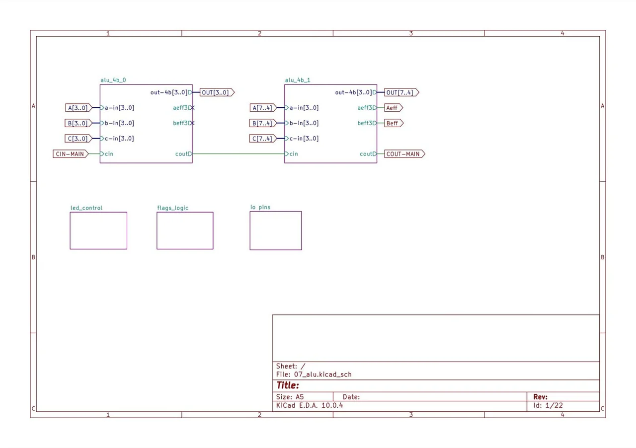
The ALU schematic behind the physical board.
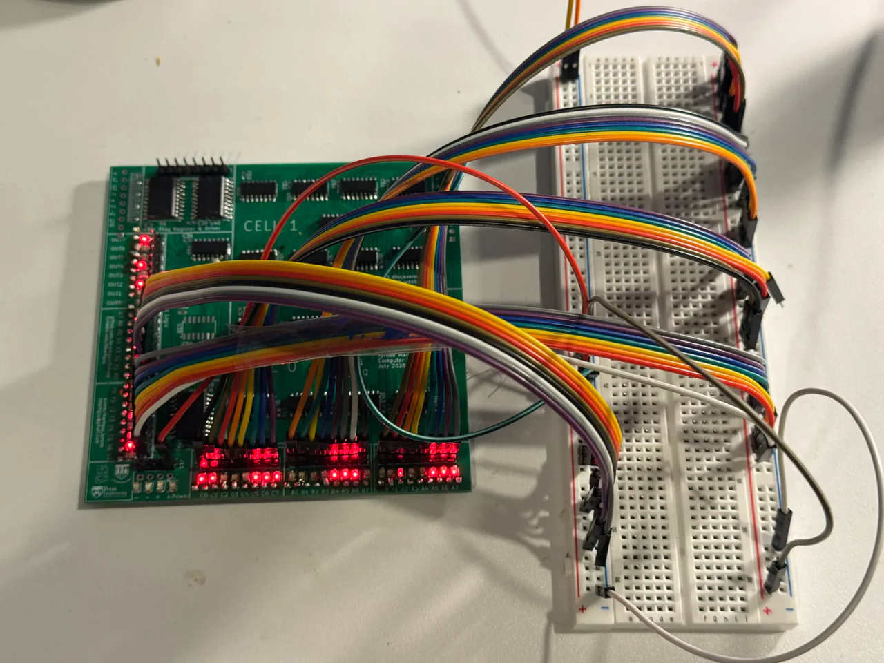
Lot 07 on the bench during board testing.